I know it has been a long time since my last post, but this recording took me a lot of effort to reach a certain degree of quality that I always strive for. So here it is and I hope you enjoy it:

For me it was a hard lesson to learn how to emphasize the melody parts appropriately, but if I listen to the result I think it was worth all the effort.

Posted by: sebion | September 25, 2012

Expression Pedal MIDI Controller(MIDI merge)


This time I’m going to present you a spin off project from EPiCK, that I’ve just created. This time it is all open source so that everyone can build one:
So what I created is a little box that forwards incomming MIDI data to its MIDI-OUT, measures the position of a plugged in pedal and add the pedal messages to the incoming MIDI stream:

The sources plus schematics can be found here: https://code.google.com/p/epick-pedal-controller


If there is interest I’m also planing to add support for EPiCKs optical pedal sensors, so that anyone can make a continuous pedal from a simple on/off pedal unit. This could also be used with EPiCKs motherboard as a pedal controller with integrated USB-MIDI interface.

Posted by: sebion | August 7, 2012

What would you pay?


Since I’ve got some requests I’m thinking about selling EPiCK as a retrofit/midifying kit for all kinds of keyboard instruments including Hammond organs, Rhodes, Wurlizer, Clavinet. If you want to support me now, which might help me to evaluate legal issues before crowdfunding, you can of course donate an amount of your choice at the ‘About’ Page.

So let us assume everything goes well and I can make EPiCK available for customers. What would you pay for it?

EDIT: I’ve got an interesting custom answer in the poll that I won’t keep secret: “Sell the plans to build it ourselves $100 US”. Of course this would be the best way to go for me, as it would not involve all the CE/FCC testing stuff, but honestly: Who except me and some rare other persons are able and willing to solder this system by hand? Besides it will be much cheaper in mass production. Also If I give away the plans I would risk piracy and that would really be a shame given the huge effort the development took me. Of course you are welcome to comment on this topic here.

Posted by: sebion | July 27, 2012

Gummy bears and an optical progressive pedal sensor


Yes you are right. I’m actually using gummy bears in my piano action to enhance its repetition behavior:

Of course this is not a final solution but a good test before I buy materials for a damper bar that does exactly the same without the ability to dry out 😉

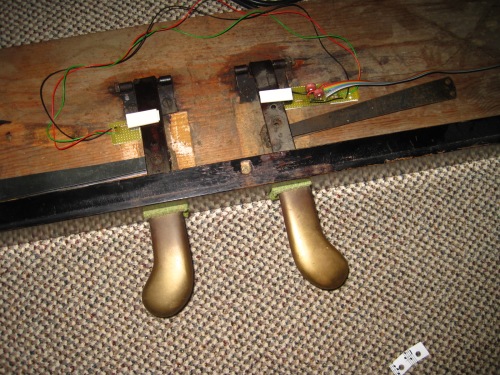
Today I soldered my very first progressive pedal sensor and attached it to the pedals that came with the modern piano action I’m currently using. They’re working much smoother than the old ones of my digital piano I used to read out (They weren’t actually designed for continuous readings but it worked nevertheless). Very stable midi values ideal for practicing half or quarter pedaling 😉

The module is connected via ribbon cable to the mainboard and you can attach any continuous or non continuous pedal controller to it (no need for optical ones, but if you need a progressive pedal controller those CNY70 controllers are the easiest option to build them). And Action:

Posted by: sebion | July 18, 2012

A modern piano action


Like I mentioned an “Oberdämpfer” is an obsolete kind of piano action, so lets test the new fabricated SMD boards on a modern piano action, shall we?


so these are the missing keys:

First we need a stable ground plate:

strengthened with aluminum profiles:
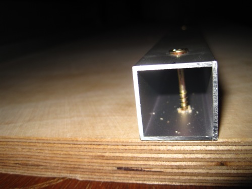
mount the keyframe on it:
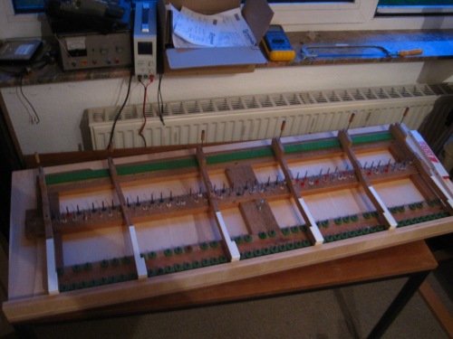
put in the action:
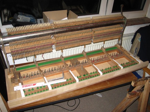
build a holding frame for the action:

glue the sensorboards on an aluminum profile. Here you can see an advantage of the new connector system. you can arrange the boards the way needed for your keyboard. small deviations from the norm are no problems:
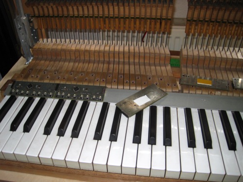
so this is the entire sensor bar on its profile:
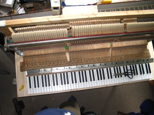
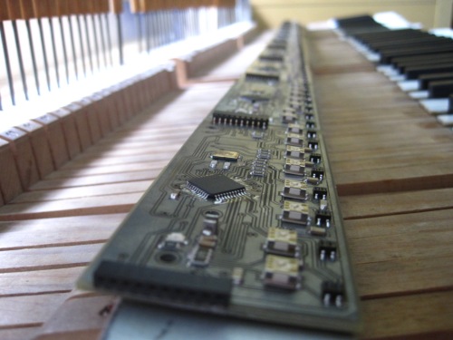
 

And the final construction (hammer stop bar is still missing):
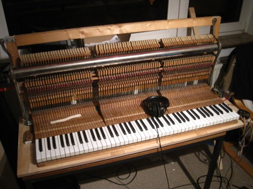
So this baby is ready for some testing, YEAH!


to be continued…


Phew! I just managed to solder the last 4 boards in a pizza oven. Now I’ve got 18 (+ the first one sided) of  them!


And the one who finds the missing sensor in this picture gets a virtual cookie:


Now a few software changes have to be made and then I hope you’ll see the new sensor strip in action!

Posted by: sebion | June 25, 2012

The new SMD sensorboard soldered


I just wanted to show you the next generation smd sensor board in it’s very flat and small smd fashion:

yes it fits the keys 🙂

it hast a backside

and is this flat (about 5 mm)

“OH PLEASE, may I play it?”

Posted by: sebion | June 10, 2012

Motherboard 2.0 manufactured


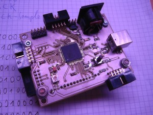
Right now I’ve soldered the new motherboard design and tested it. So far I can tell it didn’t explode and the usb bootloader seems to work:


Posted by: sebion | June 9, 2012

Reception of my very first manufactured PCBs


Today early in the morning I received the box with my very first(time in my life) professionally manufactured pcbs. So let solder ’em! shall we?

So I’ve to admit I can’t wait to do my first steps on the new AT90USB controller. Hopefully it won’t take too long till I manage it!

Posted by: sebion | June 6, 2012

Slow Motion Of The Scanchain


This time I decided to give you a slowmotion explanatory video demonstrating the new key scanning technique my SMD sensor board features. Recall that this technique is supposed to reduce power consumption by 75 % while minimizing crosstalk effects:

In the video you can see which IR leds are switched on (blue spot). The flash numbers show you when which ADC channel is read by the controller. You will notice that there are always 2 IRLEDs on: The one that was recently scanned and the one that is to be scanned in the next cycle. The switching occurs during an unused ADC cycle thus avoiding current spikes generated by the switching ruining the ADC measurement.

Older Posts »

Categories